Circuit Breaker Diagram / Circuit Breaker Residual Current Device Fuse Wiring Diagram Overcurrent Png Clipart Aardlekautomaat Circuit Breaker Electrical Network / Electrical and electronic circuits can be complicated.
byAdmin-
0
Circuit Breaker Diagram / Circuit Breaker Residual Current Device Fuse Wiring Diagram Overcurrent Png Clipart Aardlekautomaat Circuit Breaker Electrical Network / Electrical and electronic circuits can be complicated.. The distribution board is also called the consumer unit. Electrical and electronic circuits can be complicated. Circuit breakers that are used at the distribution board in houses are called mcbs (miniature circuit breakers). As soon as power is applied to the control circuit (terminals 7 and 4), the spring charging motor is energized, and the closing springs charge. How to map out, label your electrical/fuse panel.
We are looking forward to your feedback, questions and remarks. The distribution board is also called the consumer unit. A fuse is used for protection of any electrical device from overcurrent. Circuit breaker amp ratings purposely om ited f rcla y. The three parts are to be connected to form a single big circuit.
How To Install A Circuit Breaker 14 Steps With Pictures from www.wikihow.com A typical wiring diagram with dc control for a westinghouse dhp is shown in the figure below. Moving to the bottom area of the single line diagram, notice that the circuit breaker (b3) in the middle is connected to the bus in the bottom portion. Making a drawing of the connections to all the component parts in the circuit's load makes it easier to understand how circuit components are connected. This device is essential in a modern world that runs on electricity. Drawings for electronic circuits are called circuit diagrams. Variety of 3 pole circuit breaker wiring diagram. The distribution board is also called the consumer unit. The starting point for planning a switchgear installation is its single line diagram.
Making a drawing of the connections to all the component parts in the circuit's load makes it easier to understand how circuit components are connected.
Here thyristor th is called the main thyristor andth2 is the auxiliary thyristor. A wiring diagram is a simplified traditional photographic depiction of an electric circuit. Our daily work is to continue this new trend. Circuit breakers symbols for use in electrical, pneumatic and hydraulic schematic diagrams. A breaker panel box, 15amp, 20amp, 30amp, 50amp, and gfci breakers. • adjacent breakers, such as 1 and 3, and 4 and 6, are on opposite phases. breakers 1 and 6 derive power from l1, breakers 3 and July 11, 2021 october 5, 2020 by dinesh. The white wire is used for hot in this circuit and it is marked with black tape on both ends to identify it as such. Without a circuit breaker, you could find yourself dealing with household fires on a regular basis. Drawings for electronic circuits are called circuit diagrams. Making a drawing of the connections to all the component parts in the circuit's load makes it easier to understand how circuit components are connected. Protection, circuit breaker and fuses symbols. Figure 16.26 shows a simple type of static dc circuit breaker in which the thyristors are used for making and breaking the dc circuits.
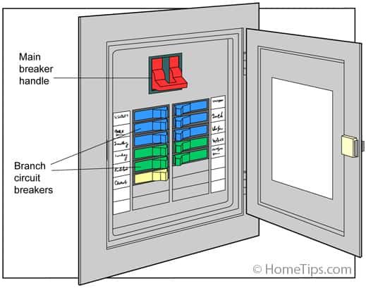
Today we show you how to map out and label your electrical panel, also called the fuse panel, or fuse box. For example, it might require a larger number of timeout exceptions to trip the circuit breaker to the open state compared to the number of failures due to the service being completely unavailable. Protection, circuit breaker and fuses symbols. This time, however, the circuit breaker is a fixed low voltage circuit breaker, as indicated by the symbol. Dead tank circuit breakers disconnecting circuit breakers
How To Map House Electrical Circuits from www.hometips.com Collaborative flowcharts, wireframes, mind maps and sticky notes. The circuit breaker acts as a safety device in the same way as a fuse. The starting point for planning a switchgear installation is its single line diagram. Electrical and electronic circuits can be complicated. This indicates the extent of the installation, such as the number of busbars and branches, and also their associated apparatus. Today we show you how to map out and label your electrical panel, also called the fuse panel, or fuse box. A circuit diagram or wiring diagram uses symbols to represent parts of a circuit. 30,000 a nominal current with natural cooling and up to 40,000 a nominal current with ipb forced air cooling.
A neutral wire is not used in this circuit.
These are some of the symbolic representation of a generic fuse in any electrical circuit. Today we show you how to map out and label your electrical panel, also called the fuse panel, or fuse box. Circuit breakers symbols for use in electrical, pneumatic and hydraulic schematic diagrams. A circuit diagram or wiring diagram uses symbols to represent parts of a circuit. Here thyristor th is called the main thyristor andth2 is the auxiliary thyristor. Working of electronic circuit breaker connect the components correctly according to the circuit diagram above.the circuit diagram that is shown above has three parts to it. 30,000 a nominal current with natural cooling and up to 40,000 a nominal current with ipb forced air cooling. As soon as power is applied to the control circuit (terminals 7 and 4), the spring charging motor is energized, and the closing springs charge. • breaker panel shown within the dashed lines. A wiring diagram is a simplified traditional photographic depiction of an electric circuit. It shows the parts of the circuit as simplified forms, as well as the power and signal links in between the gadgets. Circuit breakers that are used at the distribution board in houses are called mcbs (miniature circuit breakers). The distribution board is also called the consumer unit.
Here thyristor th is called the main thyristor andth2 is the auxiliary thyristor. The distribution board is also called the consumer unit. 5wire the new circuit breaker. The 12/2 gauge cable for this circuit includes 2 conductors and 1 ground. Our daily work is to continue this new trend.
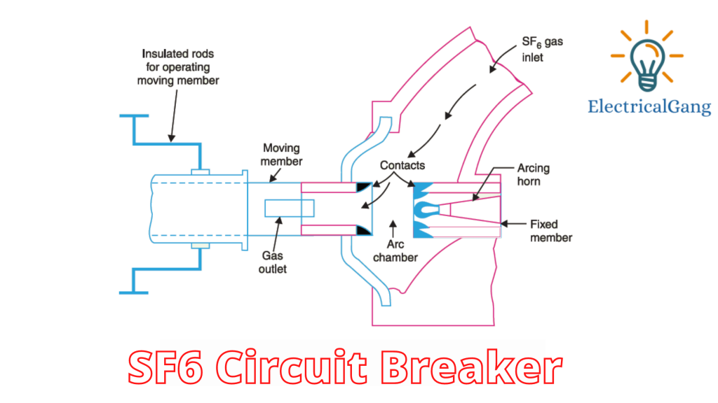
What Is A Circuit Breaker Types Of Circuit Breakers Advantages Disadvantages Of Circuit Breakers from cdn.electricalgang.com The 12/2 gauge cable for this circuit includes 2 conductors and 1 ground. The white wire is used for hot in this circuit and it is marked with black tape on both ends to identify it as such. These are some of the symbolic representation of a generic fuse in any electrical circuit. Moving to the bottom area of the single line diagram, notice that the circuit breaker (b3) in the middle is connected to the bus in the bottom portion. We are looking forward to your feedback, questions and remarks. Dead tank circuit breakers disconnecting circuit breakers A typical wiring diagram with dc control for a westinghouse dhp is shown in the figure below. How to map out, label your electrical/fuse panel.
Here thyristor th is called the main thyristor andth2 is the auxiliary thyristor.
We are looking forward to your feedback, questions and remarks. This page contains wiring diagrams for a service panel breaker box and circuit breakers including 15amp, 20amp, 30amp, and 50amp as well as a gfci breaker and an isolated ground circuit. Without a circuit breaker, you could find yourself dealing with household fires on a regular basis. • breaker panel shown within the dashed lines. Here thyristor th is called the main thyristor andth2 is the auxiliary thyristor. This indicates the extent of the installation, such as the number of busbars and branches, and also their associated apparatus. .a circuit breaker is a switching device that interrupts the abnormal or fault current. This circuit breaker wiring diagram illustrates installing a 20 amp circuit breaker for a 240 volt circuit. It has a small wire or metal which melts due to large current & opens the circuit blocking the flow of faulty currents. Moving to the bottom area of the single line diagram, notice that the circuit breaker (b3) in the middle is connected to the bus in the bottom portion. Every permanent electrical device in your house is connected to a circuit that is controlled by a circuit breaker in your breaker box, properly known as the main service panel.when you need to shut off the power to a circuit or to reset a breaker that has tripped, you have to find the right breaker for the circuit.this is about the time you begin cursing your home's builder for failing to. How does a circuit breaker work?. The starting point for planning a switchgear installation is its single line diagram.
Take some of the mystery out of those wires and switches that lurk behind the door of your breaker box with this circuit breaker. The distribution board is also called the consumer unit.